
Earlier I had mentioned my custom dash. I even posted a mock up photo:
Now that particular idea didn’t pan out, exactly, but this did.
So a few basics, I don’t have a lot of photos because I’m an idiot.
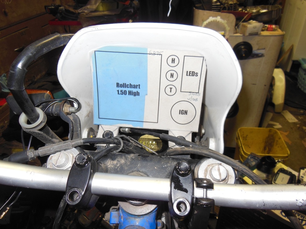
So the above template is made out of cardboard (Trader Joes Yogurt Os cereal, specifically). The real final product is made out of 16g sheet steel. I cut it out with a jigsaw, bent it in my trusty old bench vise, drilled the holes with my drill press, cut the switch hole with my Dremel, then painted it in black primer.
This is a version 1 dash, I think one day I’ll completely re-do it as I don’t like some of the details on this one.
Now that I had the dash panel itself made it was time to get to the wiring part. I find wiring to be very easy work so this was not in any way daunting to me. My goal was to have a path of retreat, at any time I can remove this dash and go back to the factory gauges. To accomplish this I used factory-style connectors sourced through www.cycleterminal.com, I was very impressed with their inventory and delivery speed.
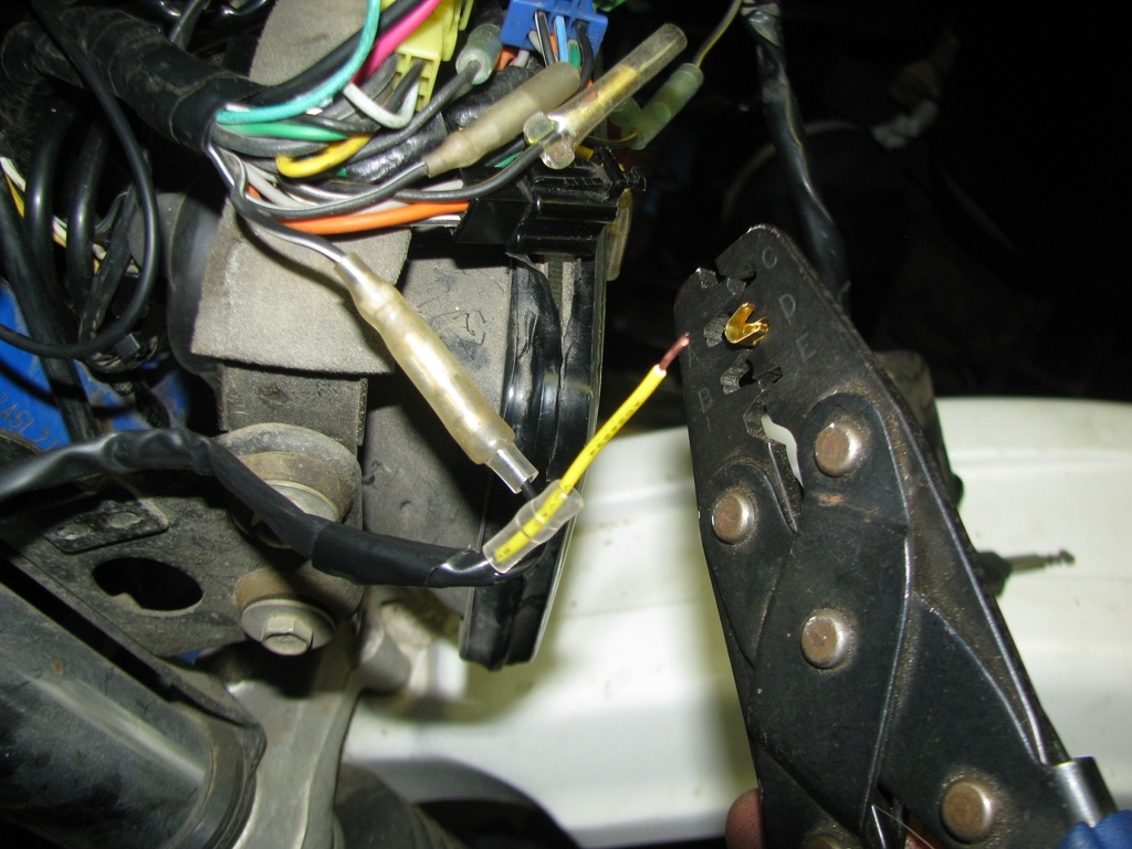
Here I am crimping a bullet connector onto a factory wire. They carry the OEM-style bullet connectors as well as the multi-wire connectors.
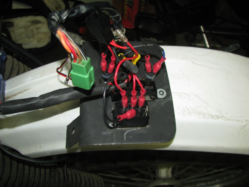
Here is the back side of the panel. It is difficult to see but all wires lead to a black six-way connector that connects to the factory dash loom. The bullet connector you see is for the high-beam indicator (Suzuki left that out of the loom).
As part of my overall project I converted to LED turn signals. This not only creates the need to go to a no-load flasher module but also requires changes to the turn signal indicator wiring. On most bikes with a single turn indicator and factory incandescent bulbs actually feed both turn signal + wires to the indicator lamp. When your signals are off the ground passes through the signals and acts as the ground path for the signal. Once you put LEDs in this no longer works.
To fix this you need to insert diodes on each of those original turn signal wires and provide a new ground. In that hardness you will see two red wires that lead to a blue wire, this is my diode lead. I purchased this for $9 from MrPulldown over on ADVrider.
The other two points to note in that photo are is the relay riveted to the dash, this controls my spot lamps. The large switch is also for my spot lamps, it is a single pole-double throw switch (on-off-on). The top position is auto, in this position the spot lamps are tied to the high beam, a flick of the high beam switch goes to low and cuts the spots out. The second position is manual on, this will allow the spots to blind people whether the bike is on or off.
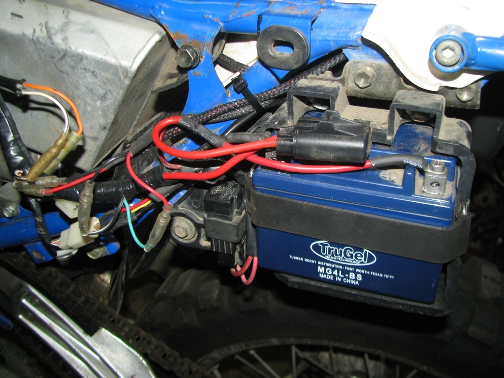
To feed these lamps, the relay control, and my Trail Tech voyager I ran a new 14g positive and negative wire from the battery. This wire has a 15A inline fuse, while this is actually over-rated for my current needs it is the same rating as the factory main fuse providing me with some spare parts commonality.
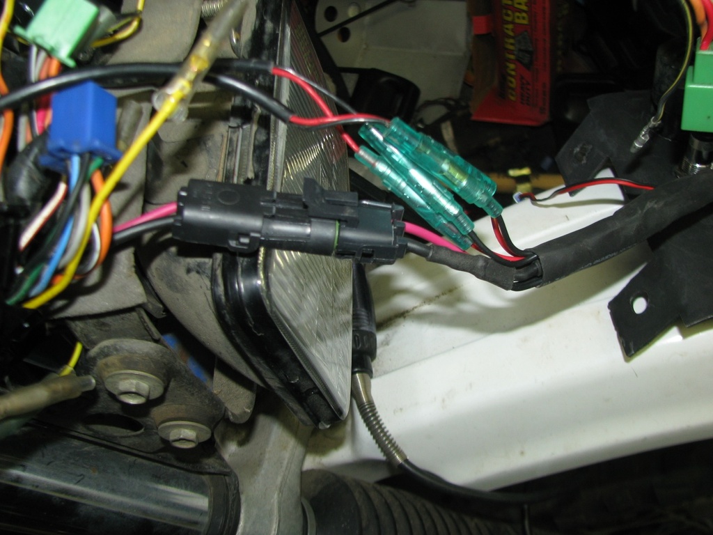
The wires end behind the headlamp in a new GM Weathertite connector. These are good for high-current and seal quite well.
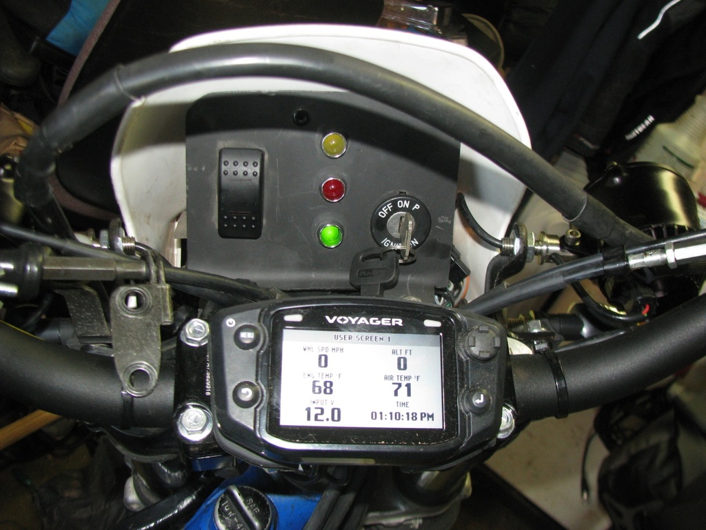
And here is the dashboard and Voyager complete and operational.